Construction Vehicle (Full Project)
The Photos
For this section of the course, we were all given an week to gather our very own reference pictures of a construction vehicle/ JCB. Due to council laws, we could not simply walk up to a construction vehicle on the street and take photos as we could be fined by the council. Due to the expense of these vehicles and health/ safety concerns, many dealerships and construction sites refused to let us take pictures of their vehicles.
There were also problems with lighting conditions and angles due to the size of these vehicles, meaning that if we found one and had permission to take pictures, the colour balance could still be off, the images could be either too light or dark and if the vehicle is not in an open area, the side, front and back shots could become skewed and generally unusable.
Eventually I managed to contact J.C.Balls who allowed me to visit the following day. They went out of their way to find an interesting vehicle and then parked it in a large, open car park which allowed us to spend an hour taking pictures of every last detail.
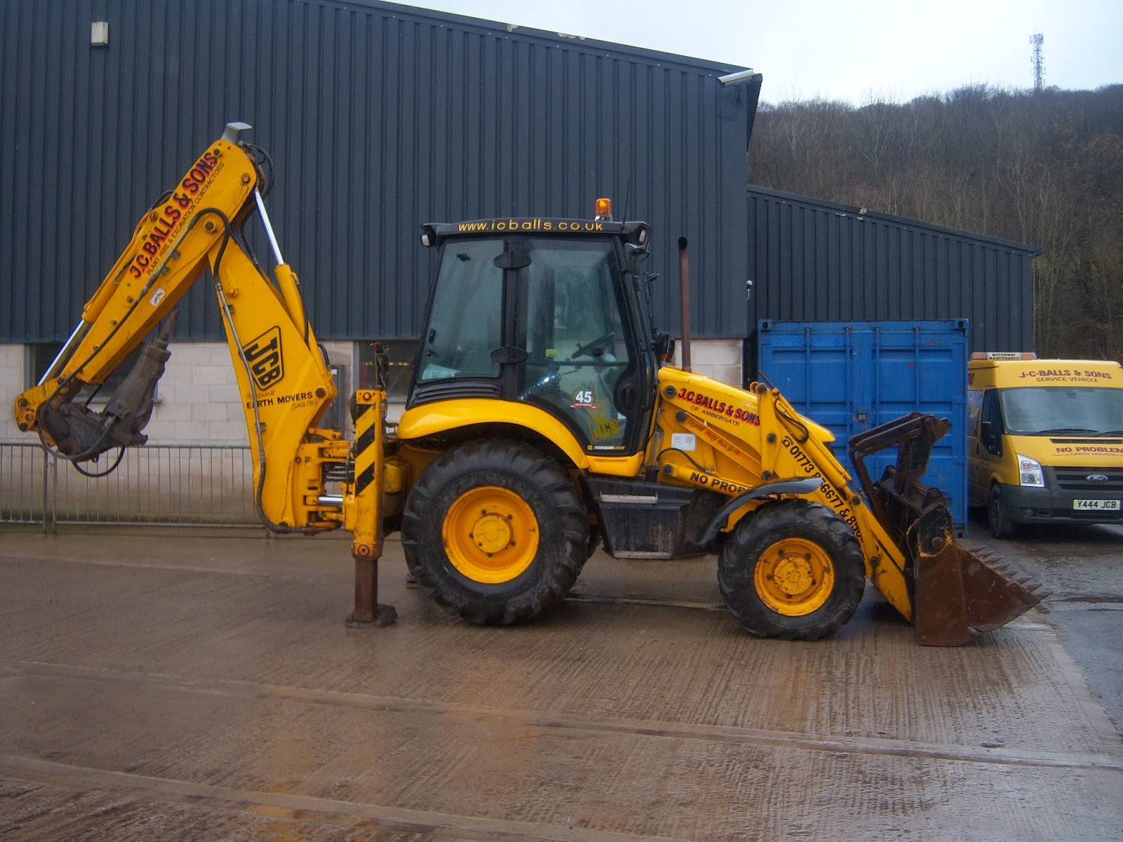
As the car park was fairly spacious, i managed to get the entire side of the vehicle in without it being at an angle and due to the lighting available, the image turned out quite clear with very little blur, making it very usable. Due to the length of the vehicle, i took two pictures of the side, one including the back piece of machinery and the other including just the cabin.
The front shot looked slightly off due to the slight angle of the front machinery and the driver-side door being open. We were not able to close this door but it shouldn't stick out to badly whilst modelling from it as reference. In the worst case scenario, i could always attempt to remove it in photoshop but the overall light levels and lack of blur should make this picture quite usable.
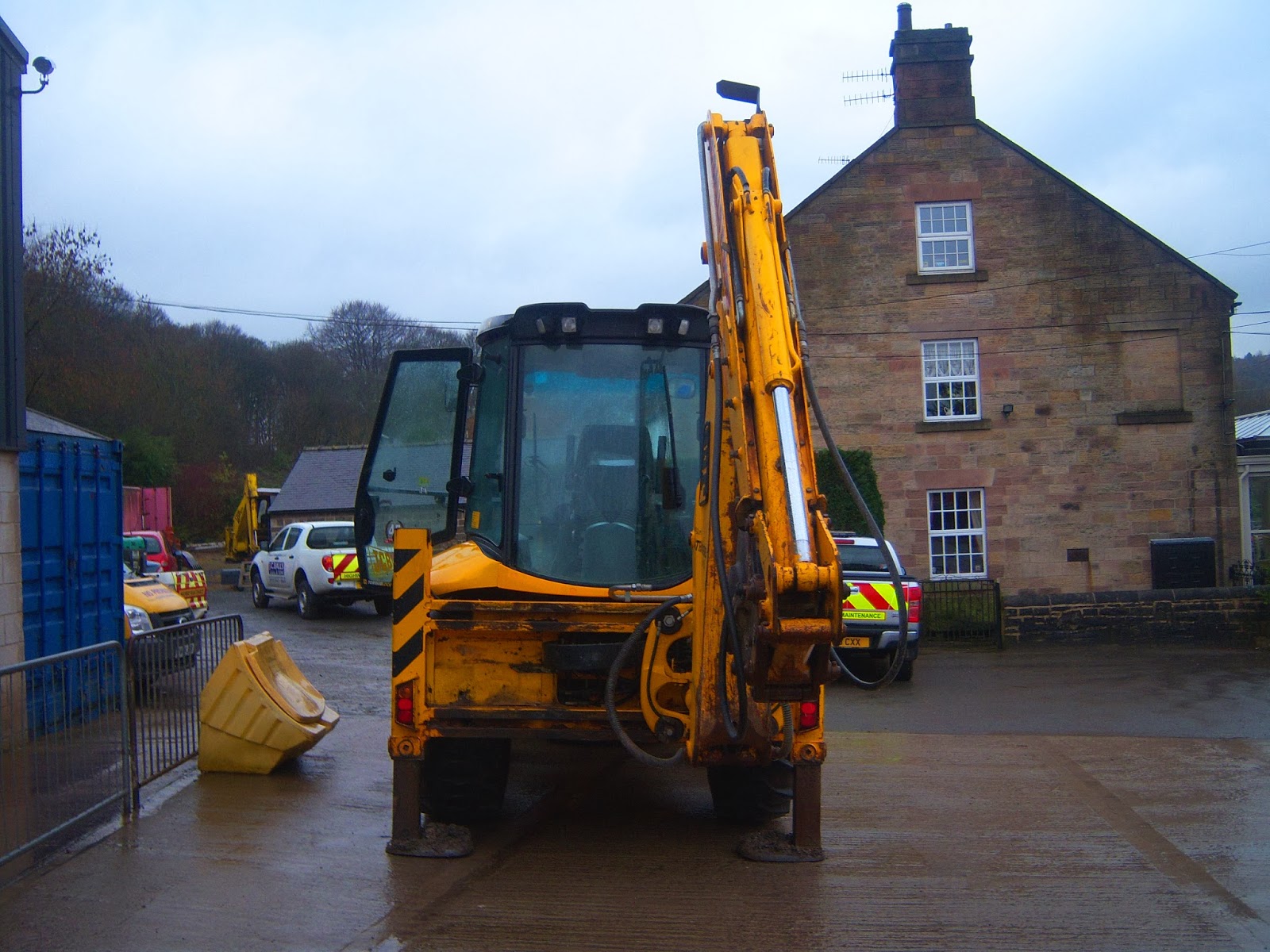
With the back shot, i had to do some slight editing as the vehicle became incredibly dark, making it difficult to see some specific details. To do this, all i had to do was apply a mask to the image in photoshop and slightly raise both the saturation and brightness until it became fully usable.
The front Perspective shot managed to create quite a nice scene behind it with a slight glow from the lighting angle making it look and feel as if it stands out from the area around it without lookout out of place. It also shows all the detail around the front and side of the vehicle without any blur which should allow me to even the trickier details in proportion.
As i took a wide range of photos of every last detail that makes up the back-hoe loader, i should have enough referances to begin creating a basic blockout of the model before adding additional details. Areas such as the hydrolic arms and general metal panels have full, closeup photoes which i can use to model from directily in an attempt to solve any perspective issues i have from the front perspective view.
This should take out almost every single aspect of guess work, making the process far less tedious and much more structured from start to finish. After finishing and then placing each component, i can alter the camera angle and simply compare the model to the real digger to check that areas such as the depth are correct throughout.
The Modelling - Extreme Basics
The first stage with the modelling was to simply setup my image-planes but due to the slight inconsistencies in the reference images, i had to make a few tweaks within Photoshop to ensure that each of the major details lined up correctly.
This was a fairly awkward test as i also had to alter the colour balances of each image to bring out as much detail as possible without over saturating them. After setting them out across a variety of layers, i could then begin modelling the very basic shapes and geometry to make up the model. I used the UDK man as a size reference just to ensure that the vehicle wouldn't be either too big or too small.
Working directly from the key three reference images as well as a lot of the extra details, i outlined all of the key geometry which define it as an engineering vehicle. I did not worry in the slightest about the detail nor optimisation at this point as the model in its current state would only be used as reference, being deleted piece by piece as i work through it.
One problem arised though; the generally curvy shape of the main tractor body was going to cause quite a few problems as the curves themselves were left down to a lot of guess work due to the vast majority of the cabin being covered up by hydraulics within almost all of my reference photos.
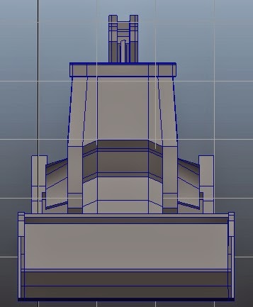
Top View
Side View
Front View
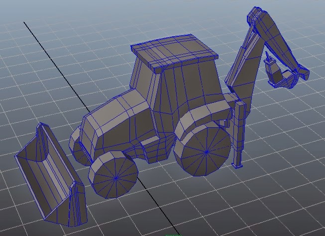
Perspective
The Modelling - Rebuilding
At this stage of the modelling process, i had been slowly replacing components of the vehicle in a section by section method, branching away from a full piece of looping geometry towards many smaller sections of detail combined to gather in the same fashion as a DIY model car. Not only does this remove a lot of the confusion, it also makes it far easier to work with as each detail can be made from scratch without having the worry about connecting geometry.
The modelling is going very nicely at this stage but i may find myself simplifying certain areas such as the rear machinery as i have only left just over two thousand Tris to fully re-make the main tractor body and wheels which could lead to some issues further down the line.
To make a lot of the components within the front and back machinery, i was to use a lot of primitive objects, extruding and generally shaping them in relation to mainly the side view as this showed the best structure, allowing me to even duplicate some sections of hydraulics which i could then mirror to the opposite side of the model which greatly simplified the overwhelming number of pipes/bars.
Although i had reference images from the scoop, a lot of this was down to guess work and a lot of extrusions, especially with the eight metal spikes on the very tip of the loader but as the mirror geometry tool is always readily available, i only had to model one half and i could then copy over any changes perfectly without any risk of errors within the geometry.
For the rear hydraulic machinery, the modelling was far more awkward as the shape of the vehicle making it near impossible to take decent reference photos of anything beyond the side panels or the tool piece itself. These components looked almost slightly twisted on my front perspective shot so i relied heavily on the closeup photos i took to detail each individual piece of geometry whilst using the slightly scewed front shot to then scale them.
Modelling the main bar pieces was incredibly time consuming due to the difficulties in gathering suitable reference but through a lot of trial and error, i eventually managed to get everything looking up to a suitable standard.
It may be rather high poly in its current state but i could probably use this to my advantage when it comes to creating the normal map as i could simply re-make the faces of each key piece of geometry and then add extra edge loops for more realistic smoothing. I estimate to have the rest of the model fully built and optimised by Tuesday as the more complicated geometry is now out the way, leaving me with a much more manageable section. I estimate roughly twelve hours more work until i can call it complete.


